| |
I do not claim to be an expert in the tuning of the QB-78’s but I have
worked on a number of them after doing a lot of research. I’d like to
thank Craig Pitts (Co2unes) for his help in the past.
The information here is a compilation of information found throughout
the forums posted by many and is nothing new for the most part, but
rather a guide put together with the things that do work and in a way
for all to understand. There is no new magic involved, and for the
mechanically inclined with a few decent shop tools, not too complex.
This Tune-up Guide is not only a plain simple tune guide but includes in
great detail sections on minor and major modifications to hot rod your
QB-78. It has diagrams and pictures as well as detailed instructions on
what to do and where as well as the tools needed to do the job. When and
if you do these mods, the responsibility is your and I am not
responsible for any damage or results that are good or bad. There are
several alternatives, tune variables and possibilities, and what you do
with them is up to you. One of the most important things to keep in mind
is that maximum velocity isn’t always the best approach.
As with any other TuneUp articles I publish, read this from beginning
to end before starting the project, maybe more that once. After you
read it thoroughly, make a determination just how much you want to do
and prepare for it.
In the first part we are going through the basic tune but as you read
through this article and review the mods, you may want to incorporate
some or all of them along the way. How far you go in modifications is up
to you. Before starting this project, be sure you have all of the
necessary tools, seals and parts needed to accomplish the task at hand.
You can order a complete tune-up kit from me that includes all of the
o-rings of correct size, composition and durometer (local hardware
o-rings will not hold up for long as a rule), new hardened set screws,
breech seal, and a length of stainless steel trigger spring that you can
cut to your desired feel.
http://www.charliedatuna.com/co2.htm
The o-rings needed:
2 each #113 o-rings NOTE: DO NOT USE BUNA/NITRILE HERE. THEY WILL
FAIL)
3 each #012 Buna (the barrel o-rings)
1 each #006 Buna for the (.22cal bolt o-ring) or the #002 Buna for the
(.177 bolt o-ring)
1 each 1/4 OD poly seal (for the breech seal).
The tools needed:
The tools needed for the basic tune are tools that most people have
around the house.
A 6” flat screwdriver
12-14” very wide blade screwdriver (for the valve
#2 Phillips
3mm Allen wrench for the stock screws and a 3/32
Allen wrench for the replacement screws. (supplied in kit)
Fine (400-600 grit) wet/dry sandpaper or a honing stone
1/2 diameter Brass or hard wood dowel/rod about 18” long or longer
For the more advanced, you’ll need to evaluate what you can or
want to do based on your mechanical abilities and the tools you have
available.
Again, please be patient and take your time, especially with any of the
mods. The time, effort and care you put into this project, whether it’s
several hours or a couple of days or even a couple of weeks will
directly affect the end performance results. OK…if you’re ready, let’s
get started.
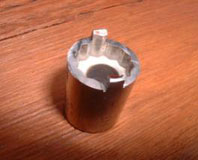
First, to make it a lot easier, you should make a valve removal tool.
Actually it’s a spanner tool. It’s quite simple, takes only a few
minutes and by looking at the picture you can see how to do it with no
real explanation. Just use an old 7/16 3/8 inch drive socket that will
fit the inside of the tube and after you make it, remove any rough edges
on the outer edges.
| |
Pic courtesy of Rich |
|
Removing the stock:
Before we can do anything, we gotta get the stock out of the way. The
guns safety (#3300) must be removed in order to take off the stock. This
is achieved by placing the safety in the full safe position and punching
the safety out with a small wooden dowel rod or drift punch from the
opposite side. Now remove the locating screw nut on the bottom of the
gun (#3200) and lift the receiver, or action out of the stock.
Removing the trigger casing assembly:
Remove the two screws (#2200 and 2300) that hold the trigger assembly
and passes through the hammer spring area from the bottom. Take notice
how and what the rear screw passes through for reassembly later.
Now let’s do a little work on the trigger to improve it.
Open the trigger assembly by removing the two case plate screws (#1814)
and remove the casing plate or cover. As you can see, it is a very
simple trigger and easy to work on. Wash it out thoroughly with a
solvent such as mineral spirits and remove any paint or loose pieces of
metal from the seer and other parts. Let it dry, then using 400 grit
wet/dry sand paper, then 600 grit. Polish all of the trigger and
mechanical contact areas, especially (#1805, 1804) to a smooth finish as
well as any other area that you can see where there has been any rubbing
contact metal to metal. The trigger spring (#1809) may be replaced with
a lighter spring to make a lighter trigger pull, but care must be taken
here so as not to be so light to make it dangerous. Some have taken a
coil or two off of the spring, but I suggest replacing it with one of
about the same length but a slightly smaller wire diameter. This can be
serviced after the gun is reassembled with the stock off if need be.
Apply a Moly oil combination thoroughly to the trigger assembly after
its reassembled and allow it to drip dry as much as possible. Pat dry
any excess lube and reinstall the Casing Plate or cover.
Looking into the small hole in the cover you can see the trigger seer
travel. This can be adjusted by adjusting the top screw at the rear of
the trigger. (#1807) Adjust it so there is about 3/32 to 1/8 inch travel
before release when looking in the hole. This can be fine tuned after
the trigger is reinstalled later when testing.
Separating the barrel from the breech:
Remove the barrel cap. Loosen the screw in the side of the barrel
support bracket and slide the barrel bracket off of the barrel and onto
the tube. Remove the barrel from the receiver by unscrewing the allen
set screw (#2800) on top of the breech between the bolt openings and
where the barrel meets the receiver. Remove the barrel by pulling the
barrel out of the receiver. Remove the barrel band from the Tube. Remove
the barrel o-rings from the barrel and discard any damaged ones. Now
would be a good time to clean the barrel using GooGone and patches with
a pull though. Also, check the muzzle crown. The surface of the muzzle
needs to be uniform around the whole muzzle. Now take a Q-tip and slide
it into the muzzle and slowly back it out. If no fibers catch on the
muzzle, it should be fine.
There are a couple of approaches to re-crowning the barrel but for most
people with limited tools, this will work. Start out by taking a pellet
and inserting it into the muzzle head first pushing it just inside the
barrel. You can take a brass Philips head screw that was large enough to
cover the surface of the muzzle (you do not want it to go into the
muzzle, but cover the outer rim) then chuck it into a variable speed
drill. You’ll want to do this slowly. Using a valve grinding compound
and then a super fine machining compound (valve grinding and finishing
compounds are available at any parts store) slowly refinish the muzzle
crown keeping the drill as straight up and down as possible. Then, take
a small piece of 600 grit paper, form it into a cone and work it a
little in the edge of the muzzle in a twisting back and forth fashion.
When you think it looks good, again, take a Q-tip and slide it into the
muzzle and slowly back it out. If no fibers catch on the muzzle, it
should be fine. Now remove the pellet pushing it out from the breech end
with a small long dowel or being careful, a cleaning rod.
Now for the cleaning of the barrel. Again, there are a several ways and
suggestions. What I do is very simple and inexpensive as well as safe. I
drip some GooGone on a soft nylon bore brush (do not use a brass
bore brush) and worked it back and forth a couple of times in the
barrel. Then I run patches with GooGone on them through it. I do this
several times until it is clean. Run a few extra clean dry patches
through it to remove the excess GooGone.
Removing the bolt assembly:
Remove the long locating screw (#0300). Beneath the bolt where you would
load a pellet is a screw and until the barrel is removed, you will not
see this screw. Remove this screw and now the breech and the tube can be
separated. Note the breech seal that sets between the barrel and the
tube. Take notice of the location of the hammer pin (#0900) and the
cocking pin (#1000) are located and remove them by lifting them out and
setting them aside.
Remove the bolt assembly by removing breech plug (# 1900). It might have
fallen out fell off when you removed the rear trigger screw. Looking
inside the rear of the bolt you will see an allen screw that must be
removed. Removing this screw will allow the bolt handle to be removed so
the bolt itself can be slid out of the action. After you remove the
allen set screw, the bolt handle will pull out of the bolt. Now you can
slide the bolt assembly out of the action.
File smooth and deburr any metal where the bolt handle extends out of
the gun along the length of the slide track the bolt slides on as well
as the hammer and cocking pin slots and polish smooth using 200-400
paper. Using a small cylinder hone or a dowel and piece of 200-400 paper
rolled into a tube, clean out the inside of the bolt chamber.
Thoroughly clean all of the parts then install the new bolt probe seal
and apply a thin coat of 100% silicone dielectric grease to the bolt
probe seal and a thin coat of moly to the bolt assembly and reinstall
the bolt, bolt knob and Breech Bolt set screw. Note…if using the new
bolt allen set screw in my kit, spot drill the bolt handle with a 3/16
drill bit just enough to form bit of a taper for the tip of the screw.
Set this aside for now.
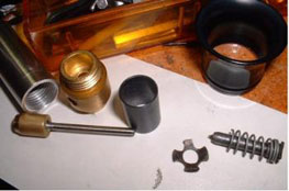
Removing the valve assembly:
Looking down into the tube you can see a slotted area that looks like a
plus sign about 2/3rds of the way down. Be sure the valve set screw (#
0500) is still in place. Using a very wide blade screwdriver,
loosen the valve about one turn counter clockwise. You may not be able
to loosen it without making a special spanner tool (see pic above) out
of a 7/16, 3/8 inch drive socket. If you are unable to loosen it,
continue on.
Remove the valve set screw (#0500). Be sure the locating screw and
the valve set screw are both removed. Now remove the valve assembly
by using a piece of a piece of ˝ inch or larger hard wood dowel or brass
rod dowel rod, or a little smaller that the tube diameter and inserting
it into the front of the chamber and with the rear of the tube placed on
a piece of wood, tap the valve assembly out through the rear of the
chamber. This may require some effort initially, especially if you were
unable to loosen the valve, but once it breaks loose and starts moving
it will it will come out easily. It can be driven out from the rear
also, but be sure the inside plug (#0200) is in place in the tube (and
not secured with the locating screw) so as not to damage the valve stem.
Let’s do some work on the breech:
Mod available…see modification section for additional information:
Now deburr the breech port (Just above #1500). Deburr the inside of the
breech (#1200) paying special attention to where it is drilled for the
transfer port and barrel set screw. Slightly bevel the forward breech ID
where the barrel slides in and polish this area. Polish this ID of the
breech using 220-320 emery cloth, removing the sharp surface edge.
NOTE: Special emphasis needs to be placed on the inside of the tube
where the valve set screw threaded hole is and also the transfer port
inner edges. Although a little difficult to reach and clean up, unless
you do, you can almost bet on cutting the seals when installing the
barrel. If the above is done properly, you will never cut another set of
o-rings (#2700) while installing the barrel.
On the bottom of the breech you will see where it is beveled to fit the
tube. (Just above #1500) Lightly file the sharp raised to create two
flat edges about 1/32 inches wide on each side of the port. This
provides the seal with a flat surface contact area and chances are you
will never blow another breech seal.
As for the breach porting and bolt probe extension, they go hand-in-hand
(see mods), but in many people’s opinion, really doesn’t seem to enhance
performance enough to justify the extra work. It only adds about 5-10
fps at most and while at the same time, reduces usable shots by using up
or dispensing available Co2 much more rapidly.
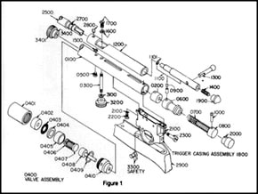
Matching of the breech port to the barrel port is important for smooth
uninterrupted flow of Co2 from the breech to the barrel. (See figure 1
B-2)
Now about this valve thingy.
The valve is a two piece assembly that is screwed together. To separate
the valve assembly, unscrew the two halves. Unless you were able to
loosen the valve in the earlier procedure, it is going to be tight
because they are LocTited together, or at least mine were on both
QB-78’s. Care must be taken not to damage the surfaces of the valve. I
used a piece of rubber hose and held it in a vise and used a flat file
edge (until I made the spanner) as a wide screw driver on the end,
although any sturdy, flat wide tool/blade can be used. Once it breaks
loose it will unscrew easily. Note: when opening the valve, take notice
how it is assembled on the inside. Thoroughly clean and lube all of the
parts with a fine coat if 100% Dialectic Grease. Install the new seal
and reassemble, but do not tighten it completely. Leave the assembly
about ˝ turn loose. If you tighten it, you will more that likely damage
the seal when you install the valve.
Mod available…see modification section for additional information:
Below, if you have the tools and are accomplished enough to perform
the task, is a modification for the valve that can be done before
assembling and lubing the valve. This mod is to improve the flow of the
propellant for more efficiency. Thoroughly clean all of the parts that
are on the inside. Lube the valve body (#0400) using Air Tool Oil, or
preferably 100% pure dielectric silicone oil and reassemble.
Take part #’s 0407/0408 and modify to the specifications in the diagram
Figure-3 C-1 and C-2below.
The Tube:
Next, finish honing and cleaning out the tube assembly. To do this, I
use a 3/8 inch dowel 16 inches long with a slot cut in one end about 4
inches long. I then place a folded in half four inch wide piece of 200
grit wet/dry sand paper and place the other end in a drill and polish it
making sure the paper is wet and rinsing off the paper as you do it. Now
do the same thing with 400 grit paper. Using a clean cloth and dry
thoroughly inside and out. Lube the inside of the chamber with
preferably 100% silicone oil or a thin film of 100% dielectric silicone
grease or if nothing else, a good Air Tool oil.
Well, I guess we are ready to put this mess back together again.
Putting it back together is basically the reverse of disassembling it.
Install the Valve:
Be sure the valve has not been tightened up. It should be about ˝ turn
loose. Insert the valve assembly into the front of the chamber tube.
Line up the threaded screw holes on the valve with the two holes in the
tube on the same side of the tube (the bottom) with the single small
slot. The valve port hole in the valve should be in line with the two
holes on the side (the top) with the long slots. Carefully push the
valve assembly into the chamber slowly until the valve port hole reaches
the first small hole in the tube. Using a small screw driver or pointed
punch, line the holes up, and when it’s centered in place, reinstall the
valve set screw (#0500). Now, using your wide blade screw driver (or
spanner) go down through the front of the tube and tighten the valve.
Tighten it pretty snug.
Now place the inside plug (#0200) into the rear of the tube and install
it with the threaded holes side inserted first. This plug is threaded on
both sides but different sizes. The larger of the two holes should face
the bottom of the tube, the side with the small slot. Slide it in until
you can see the holes in the tube just ahead of the slots.
Install the locating screw (#0300) into the threaded hole next to the
valve set screw on the bottom of the tube and tighten.
Install the new breech seal/gasket (#1500) in the seat in the tube.
Note: Do Not Lube This Seal.
Now you can reinstall the hammer spring assembly (#s 0600-0700-08000) in
through the rear of the chamber. Install the hammer pin (with the round
head goes in the front hole) and the cocking pin (with the square head
goes in the rear hole).
Place the breech over the tube aligning the hole for the breech hold
down screw. Be sure the two pins (cocking and hammer) are in their slots
in the bolt and be sure the breech seal is in place. When all is
aligned, install the hold down screw (and washer if it has one)
(#1600-1700). Some don’t. Do not tighten this screw yet.
Take the time at this point to be sure that everything seems to be in
its right position.
There is a mod using a Ľ thick spacer between the cocking block (#0800)
and the tube plug (#2000) to increase power by allowing a transfer of
more Co2. You can do that now.
Now install the trigger. Do not cock the gun until the trigger screws
are in place and snugged up. Install the front screw first and just
loosely tighten it, then after installing the tube plug (#2000) (see
above) and breech plug (#1900) and aligning the holes, install the long
rear trigger screw and snug it up. Snug up the front trigger screw.
Install bolt handle (do not tighten the bolt handle set screw yet
because we need to slide the bolt back to tighten the screw under the
bolt) and cock it and slide the bolt back and forth a few times to be
sure it travels freely back and forth.
If all feels well, remove the rear trigger screw enough to release the
breech cap and the bolt handle and slide the bolt back, tighten the
screw in the breech and, install the bolt handle and tighten the allen
set screw. Now tighten the rear and front trigger screws. Now you can
cock and “shoot” several times to be sure all is working properly.
You can fine tune the trigger at this by adjusting the top screw using a
tiny screw driver and cocking and pulling the trigger. Be careful not to
set it so close as to make it dangerous.
Install the barrel:
Install the barrel seals on the barrel without any lube. After the seals
are installed on the barrel, lube the outer seal surfaces with a fine
coat of 100% dielectric silicone grease. Just prior to installing the
barrel, put a fine coat on the breech where the barrel slides in.
Install the barrel clamp over the barrel. When installing the barrel
into the breech, do not twist the barrel (twisting it as you install it
could very well damage the seals). Just slide it in being careful not to
damage the seals as they pass over the holes. If need be, you can
depress the seals at those points with a small screw driver to help get
past the edges. Slide the barrel clamp down over the tube and tighten
the screw slightly. Just snug it up because it will break if over
tightened. It does not need to be tight.
Finally we’re going to put the stock back on. Slip the action into the
stock and install the washer and nut and tighten. Install the safety by
depressing the spring pin that you can see in the hole with a small
screw driver and while depressed, slide the safety through the hole from
the bolt side.
The bolt may still be a little difficult for around 500 shots but it
will loosen up as it breaks in and after about 500 or so shots and
becomes much easy to work.
The only real maintenance to these guns is a few drops of silicone lube
(I use a small rag with silicone shock oil) applied inside the air
chamber (where the co2 powerlets go) every 1000 shots or so. I also
sometimes spray my pellets with a light coat of silicone spray as co2
has a drying effect unlike o2. You may want to put a drop of lube on
your finger tip and touch it to the tip of the co2 cartridges when
installing them.
| |
Figuer 1 |
|
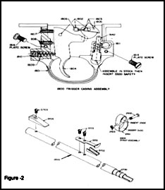
Figuer 2 |
|
|
Major
Modifications for the QB-78 |
As for the breach porting
and bolt probe extension, they go hand-in-hand, but in many people’s
opinion, really doesn’t seem to enhance performance enough to justify
the extra work. It supposedly only adds about 5-10 fps at most and while
at the same time, reduces usable shots by using up or dispensing
available Co2 much more rapidly. That being said, if you do decide to do
the breech mod, then you should also do the bolt mod.
Bolt Mods: you can do one or the other…if you do the barrel to
breech mod you should do the major.
Minor Bolt Mod: With the bolt out you will see a small port in
the front of the bolt probe as well as the hole looking at the end of
the probe. You can, if you like, carefully enlarge the oval hole in the
bolt probe a little and even slightly enlarge the drilled passage threw
the probe. This will increase the velocity without changing the number
of shots per fill.
Major Bolt Mod: The alternative, major surgery on the bolt.
Remove the bolt o-ring. You will want to cut off the existing bolt probe
in front of the bolt sealing o-ring as shown in Figure 3, D. You can cut
it off just a little further ahead so as to have a little more drilling
room in the front of the bolt, but the end result that you want is the
total length. Smooth out the rough edge where you cut it off. Now using
a 1/16 inch drill bit, drill into the front of what’s left of the
existing probe a short distance. When all is set, you can use a 1/16
inch drill bit cut off to the proper length (see the diagram for the
total length) making sure the end that pushes the pellet is flat and
true. What is important here with the probe is that the pellet when
pushed into place by the probe is past (in front of) the port by at
least an eighth of an inch and the seal itself is behind the port. Use
Loc-Tite to secure the probe in place. Using a 200 or so grit paper
remove any sharp edges on the probe so as not to damage pellets and
keeps them straight as it pushes the pellet home. Your new probe is
complete.
|
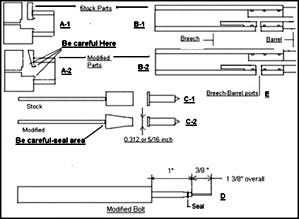
Figure 3 |
Barrel to Breech Mod:
Looking at the barrel port you will see that it is a tapered and an
elongated hole. The object here is to use a Dremel Tool with a tapered
grinding tip (some people use a drill bit) and make the taper a wee bit
larger. When doing this, care should be taken to not go beyond the edge
of the metal to a point where you get into the o-ring groove. After the
tapering is done, you then want to use you Dremel Tool with a metal
cutting tool to elongate that hole just a little more on each end…not by
much.
Close matching of the breech port to the barrel port is important for
smooth flow of Co2 from the breech to the barrel. (See figure 1, item
B-2) Note: do not cut the breech port to match
without serious evaluation and measurements as you might have a sealing
problem with the breech seal to the tube.
Valve modifications:
There are several things that can be done to the valve to improve
efficiency and flow. The ultimate objective is to move as much measured
propellant as fast and as smoothly with the least amount of restriction
as possible. How much modification you want to make is up to you. While
doing these mods on the valve (and any other put of the tune for that
matter), take your time and work with care.
Carefully review figure 3 and compare A-1 and A-2 and identify with them
the differences in the port of the stock valve and the modified valve.
Also do the same with the valve stem, C-1 and C-2.
Let’s work on the valve stem first. Most people don’t have a lathe, but
these procedures if done carefully can be done with a drill press or
even a drill that is secured or if you have another pair of hands. While
working on the valve stem and tapering it, it is important that you do
not get it to hot as it will damage the valve stem seal shown on
figure-1 (seal surface) and the Co2 will leak out of the gun.
We are going to taper the brass on the valve stem (#0408). Draw or cut
a fine line around the brass about Ľ of the way down from the seal end
of the valve stem. This will be your upper limit although it doesn’t
need to be precise. Using which ever tool you have available, chuck the
valve stem into it. Using a fine cutting file, carefully while it is
turning, taper the brass from the upper point where you drew the line to
the end until the end has a diameter of approximately 5/16 inch. If you
have a micrometer and want real precision, use the numbers on the
picture. As you are doing this be sure to keep the brass from getting
hot by stopping and applying a wet rag to it. After you reach that
point, take a piece of 400 grit wet/dry sand paper and smooth it up real
nice and where your starting line was, bevel it with the paper and take
off a little of the surface up to the top where the seal is being
careful not to come in contact with the seal itself.
After you have finished with the valve stem, take the piercing pin
(#0407) and chuck it up. We want to cut the spring seat down to a point
that it matches the diameter of the tapered end of the stem valve. After
turning it and filing it down, smooth it out with the 400 grit paper
also. Looking at the piercing end where the sharp point is. Taking care
not to damage the point itself, take off the sharp edge right behind it
where it goes from a taper to the shaft just enough to round it a little
for smoother flow.
Next we’re going to do a little work on the exhaust valve body (#0410).
Looking at Figure-1 A-1 and A-2 you can see that it has been tapered
inside. Tapering this must be done with care. Remember that the breech
seal sits on this port. You don’t want to open up the port or hole at
the top (start just below the edge) and as you taper it inside, you need
to be very careful not to go too far out to the edge at the bottom of
the taper. At the bottom of the taper I would stay between 1/32 and 1/16
of an inch from the seal seat wall. If that seal seat is damaged, it is
junk. To do this part of the mod it’s best to use a Dremel Tool with the
tool #N (followed by a degree mark) 194. After you have it tapered,
polish it out using a thin long nail and a piece of emery paper or 400
grit paper. When you are finished clean it thoroughly.
It’s time for a little hole punchin’ in the main body, the aluminum
shiny silver piece. Ya gotta be careful here. Look at the front of the
body where the large screwdriver slots are. In the center is the hole
where the piercing pin protrudes. Mark the flat surfaces evenly in each
quadrant just a little in from center between the inside and outside of
the valve. Looking at the picture below will give you a general idea.
Drill these holes using either a 3/32nds or 7/64ths inch drill bit. Be
sure when drilling these hoes that the drill bit does not go toward the
outside of the valve but angle it ever so slightly toward the inside of
the valve. If it happens to goes through the outside wall you can just
throw the Valve Body away.
|
 |
Now look at the washer
(#0404). We want to modify this washer a little also to allow the volume
to flow more freely. Below on the left is the washer stock and on the
right is the washer modified. It’s just a matter of putting notches in
the washer on either three or four sides. After you grind or file them
out, smooth out the rough edges by laying a piece of 400 grit paper on a
flat surface and polish it. I’m not very good at this graphics thing,
but you get the idea.
|
 |
When assembling the valve,
there are some parts that you may or may not reinstall. You do not need
to install the filter (#0402), and the screen (#0403). With that in
mind, be sure to clean everything thoroughly when assembling the gun so
there are no contaminates inside and especially keep the tube clean
inside and when installing cartridges, always wipe them off first. If
you are going to bulk fill, install a fine mesh screen filter in the
line somewhere. I put mine in the inlet side of the shutoff valve. You
may also want to find a slightly heavier spring for the valve but it’s
usually not necessary. Ok…lube the valve as described in the tune
section and reassemble the valve with the new o-ring and remember not to
tighten it up yet.
After this modded valve started leaking real bad, Rich had to remove
some damaged parts and spring. Notice the destroyed filter screen.
|
QB-78 Valve Pic courtesy of Rich |
That’s it for the valve
body. You can bet it will breathe a whole lot better now. I’ll bet
you’re glad to be out of here huh? So…how ya doin’….are ya still with
me…or did you get lost back there somewhere????
So now what will this entire project do for you? This should improve the
velocity considerably depending on what all you elected to do. If all
was done and done well you can expect a velocity in the area of
somewhere around 680 or so up to 725 fps in .22 caliber on a day with
temps in the 75-85 degree range with a fully charged with liquid Co2
chamber.
Ok…now that you have all of this completed, you can go back to the first
section for the assembly instructions.
So…there you are my friends….courtesy of …
Charlie
E-mail: CharlieDaTuna@Charter.net
Web Site: http://charliedatuna.com/
A tune up kit is available and can be ordered on my website for the
QB-78 and Crosman 160 that includes all of the necessary parts needed to
do a complete job that includes the 0-rings of the correct size,
composition and durometer (hardware store o-rings don’t hold up for
long), breech seal, new hardened allen set screws for the barrel and
bolt handle, and a new trigger spring that you can “adjust” to fit you.
http://www.charliedatuna.com/co2.htm |
|